mangel (@mangel@social.xip.es)
Bueno, pues parece que todo ha salido bien.
A la pobre #RaspberryPi que hace de servidor se le hacen cuesta arriba las actualizaciones, pero aquí sigue tirando.
Show Original Post
publicvoit (@publicvoit@graz.social)
The #OpenPrinter Is a #RaspberryPi Zero W-Powered, Fully-Open, Highly-Flexible #Inkjet #Printer
https://www.hackster.io/news/the-open-printer-is-a-raspberry-pi-zero-w-powered-fully-open-highly-flexible-inkjet-printer-30948a1787cc
The decision by #MegaCorps to follow the #enshittification path of things forces us to re-gain control over various parts of our life one by one.
Please, creative #hackers of this world, more of that! 🙇
#OpenHardware #RPi #InkjetPrinter #DIY
Show Original Post
Verfassungklage (@Verfassungklage@troet.cafe)
Das kann der neue #RaspberryPi500+ besser.
Es gibt etwas Neues von #RaspberryPi: Der "Tastenraspi" #Raspberry_Pi_500+ kommt als #Luxusversion mit bunt leuchtender Tastatur, eingebauter SSD und 16 GByte RAM. Unter der Haube steckt ein #RaspberryPi5, genau wie beim Vorgänger #RaspberryPi 500. Wir zeigen, was der 500+ besser kann.
https://m.youtube.com/watch?v=LSLl5LD5oRQ
Show Original Post
c2c2_ (@c2c2_@mastodon.social)
Ran new #cat6a cables, but they will not power my #raspberrypi with POE hats. Cat6, no problem. Cat6a will power other devices. Got to be that hat but over my head as to why this would be the case. Never seen this before. #selfhosting #selfhosted #homelab
Show Original Post
kkarhan (@kkarhan@infosec.space)
@r @fluffykittycat @flower Obviously people have used the #RP2040 for many projects and given it's ease of programming, low price, excellent documentation and easy availability it's no wounder it does put pressue on #ATmega / #ATtiny, #Arduino, #Teensy, etc.
- At least for low volume productions and prototypes as proof of concept.
#RaspberryPi shure are more and more targeting #embedded & #industrial clients given they do in fact disrupt the market as one can get proper #documentation and #tools without paying $$$$ upfront (AND sign NDAs) just to be able to boot #Linux on it.
- And competitors fail at understanding that this makes #Broadcom look good and is their entry-way into acquiring new clients. Because selling hardware purely off specs may work in #amd64 land where shit's legacy and the way things work is so entrenched that basic stuff just works as in booting. #ARM and even #ARM64 fail at having that level of #standardization.
OFC the #Pi0 / #Pi0W / #Pi0W2 doesn't need to innovate since every competitor isn't even trying to compete but merely farting out boards with 0 documentation and some halfassed boot images and no post-sales support so they keep dominating by virtue of being the only ones that just work...
Show Original Post
h4ckernews (@h4ckernews@mastodon.social)
Testing the Raspberry Pi 500's new mechanical keyboard
https://www.jeffgeerling.com/blog/2025/testing-raspberry-pi-500s-new-mechanical-keyboard
#HackerNews #RaspberryPi500 #MechanicalKeyboard #TechReview #RaspberryPi #HardwareTesting
Show Original Post
benzogaga33 (@benzogaga33@mamot.fr)
13 Amazingly Innovative 3D Printed Cases for Raspberry Pi I Came Across https://itsfoss.com/raspberry-pi-3d-printed-case/ #RaspberryPi
Show Original Post
benny (@benny@mastodontech.de)
#Proxmox has been running on my #ZimaBlade 2 for a week and everything looks very stable. I’m considering migrating #HomeAssistant from my #raspberrypi #k3s cluster into a Proxmox VM and using the Home Assistant OS Version. Something I need to consider?
Show Original Post
ngate (@ngate@mastodon.social)
Oh, the irony! 🤖🔒 A cutting-edge #AI model supposedly trapped inside a Raspberry Pi, but in reality, it’s the poor reader tangled in the web of #JavaScript and #cookies. Who knew the real intelligence was figuring out how to enable browser settings? 🍪💻
https://blog.adafruit.com/2025/09/26/ai-model-trapped-in-raspberry-pi-piday-raspberrypi/ #Irony #RaspberryPi #BrowserSettings #HackerNews #ngated
Show Original Post
h4ckernews (@h4ckernews@mastodon.social)
AI model trapped in a Raspberry Pi
https://blog.adafruit.com/2025/09/26/ai-model-trapped-in-raspberry-pi-piday-raspberrypi/
#HackerNews #AI #RaspberryPi #MachineLearning #TechInnovation #EmbeddedSystems
Show Original Post
diyelectromusic (@diyelectromusic@mastodon.social)
I've posted an update to my MiniDexed SSD1306 based IO board for the Raspberry Pi.
https://diyelectromusic.com/2025/09/27/minidexed-raspberry-pi-io-board-v2-design/
#RaspberryPi #MiniDexed #SynthDIY #MIDI
Show Original Post
2025 (@2025@diyelectromusic.com)
MiniDexed Raspberry Pi IO Board V2 Build Guide
Here are the build notes for my MiniDexed Raspberry Pi IO Board V2 Design. The previous version can be found here:
- Version 1: MiniDexed Raspberry Pi IO Board.
- SSD1306 Version: MiniDexed Raspberry Pi IO Board – Part 2
- HD44780 Version: MiniDexed Raspberry Pi IO Board – Part 3
Warning! I strongly recommend using old or second hand equipment for your experiments. I am not responsible for any damage to expensive instruments!
If you are new to electronics and microcontrollers, see the Getting Started pages.
Bill of Materials
- MiniDexed SSD1306 IO Board V2 PCB (GitHub link below)
- 1x SSD1306 OLED 132×64 display, pin order SDA, SCL, VCC, GND
- 1x GY-PCM5102 module
- 1x H11L1 optoisolator
- 1x 1N4148 or 1N914 signal diode
- Resistors: 1x 220Ω, 1x 470Ω
- Capacitors: 3x 100nF, 5x 10nF
- EITHER: 2x 3.5mm stereo TRS sockets (see PCB and photos for footprints)
- OR:1x 3.5mm stereo TRS socket and 1 5-pin DIN socket (see PCB and photos for footprints)
- 2x tactile buttons: 6x6x12 mm (suggested, see notes)
- 1x switched rotary encoder (see PCB and photos for footprint)
- 1x 2×20 GPIO extended header socket
- Pin headers
- Optional: 1x 6 pin DIP socket
Build Steps
Taking a typical “low to high” soldering approach, this is the suggested order of assembly:
- Diode and resistors.
- DIP socket (if used) or optoisolator (if not).
- TRS socket(s).
- Disc capacitors.
- GY-PCM5102.
- 2×20 way extended GPIO header.
- OLED display (maybe – see notes).
- Tactile buttons.
- Rotary encoder.
- DIN socket (if used).
Here are some build photos and additional notes.
Normally I would recommend the use of a DIP socket to protect the chips used, but in this instance, if this board is to be used with a case it may be that a DIP socket raises the optoisolator too high.
For once, I opted to skip the use of the DIP socket and soldered the optoisolator directly to the PCB. But the photo below shows a build in progress using the socket.
The MIDI IN socket is a dual footprint TRS or DIN mount. I’m using TRS here, so that is soldered on at the same time as the other TRS socket. If using DIN, then that should probably be the last thing to be soldered.
Unlike the previous board, this one uses the audio output pins of the GY-PCM5102 module. The simplest way to mount the module is the fix the pins as shown below and then fit the module over the top.
Not all the pins need to be connected, but the photo shows the minimum number required and their position.
I’m suggesting 12mm high 6x6mm tactile buttons (that is 12mm total height, so around 8mm button height) but the exact height will depend on the encoder used and where any case would sit height wise with the encoder, display and buttons accessible.
Although I’m not using the extended pins of an extended GPIO header, they are slightly taller than a non-extended header which is useful here. I’ve just cut off the excess pin lengths once fixed on. Being able to cut off the outer row of pins also makes soldering the inner row a bit easier.
I’ve used longer pins for the display which allows me to set the height to a suitable level to fit with the height of the encoder and buttons. I’ve soldered them to the PCB and will add the display and trim the pins down to size once I know how tall I want to make it.
Here is a side-on view. As just mentioned, I’ve soldered the long pins in place for the display but won’t solder the display itself in place until I know the exact height I’ll need. As can be seen below it is unlikely to need the full height of the longer pins.
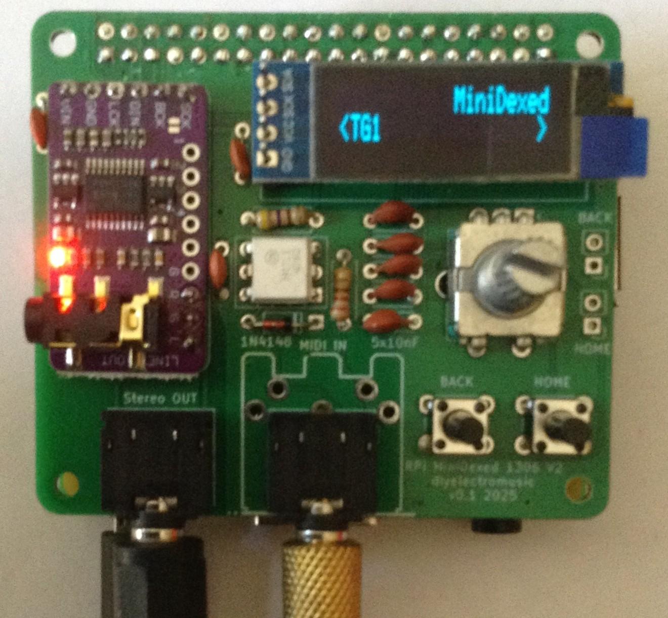
The completed board looks something like this. There are optional pin headers for the two buttons either in addition or instead of the buttons themselves, but I’m not using them here.
Testing
I recommend performing the general tests described here: PCBs.
PCB Errata
There are no known issues with this PCB at this time.
Enhancements:
- None
Find it on GitHub here.
MiniDexed Configuration
The MiniDexed configuration is unchanged from the first version of the board. Details can be found here: MiniDexed Raspberry Pi IO Board – Part 2.
Closing Thoughts
I’m really pleased with this update. It already feels a lot slicker than the first version.
It remains to be seen if this is easier to design a case for, but at the very least, not having a large gap for a MIDI DIN socket I’m sure will be an improvement1
Kevin
#midi #minidexed #pcb #raspberryPi #ssd1306

Show Original Post