GuillaumeRossolini (@GuillaumeRossolini@infosec.exchange)
This morning my ISP had an outage and I restarted their router, which happens to power my rpi0 with the web server for this project
And I forgot to restart that web server, so I lost all data from today
But before that, it was performing beautifully. There were 844 records for each node since last night, like clockwork. I happen to have cleared my previous data last night, so all the nodes were running and already on a stable mesh at the time.
Each sensor has been broadcasting its readings every three seconds, at which point my server decides to ignore most readings until the 1 minute mark (per sensor) and I’m happy that not one minute was lost for half a day of recording
I am less happy that after the web server was restarted, none of the microcontrollers found it by themselves. It looks like the entire mesh collapsed because the root node couldn’t bridge both networks again.
I understand that the root node didn’t restart the bridge between both WiFi (I didn’t set it up that way), but I would have thought that the iot mesh should have continued independently? Perhaps because it is declared as the root node? I’ll have to test this more.
I reset the ESP32 root node and it picked up the home WiFi fine, but none of the probes connected to it again (this mesh should have self healed within minutes, at most)
I went around the house to reset each ESP8266 node and yes, that is when the mesh self organized again and I started seeing the web server collecting readings again, as their BME680 sensor finished its self calibration routine
#meshnetwork #AirQuality #esp32 #esp8266 #bme680 #raspberrypi

Show Original Post
GuillaumeRossolini (@GuillaumeRossolini@infosec.exchange)
Latest news is that I got my brain into embedded thinking mode
I changed the way I determine if a sensor reading is worthy of archiving
The way I set up my probes, each #ESP8266 send its readings as fast as it can (that’s every 3s) to the entire mesh and the root node, the #ESP32, forwards them across WiFi networks over HTTP to my #RaspberryPi Zero W
The rpi0 then decides what readings to keep and what to toss
The naïve strat
The way I was deciding what to toss was, until yesterday, an SQL query doing a GROUP BY on the node sending the readings and checking the MAX date for its readings
The database file is already several dozen MB in size and growing by almost that much daily (I’m stress testing my system),
Even with a proper SQL index, the SDCard has to read a lot of information on every incoming sensor reading (SQLite is a file based system, there is nothing in RAM), just to decide what to keep and what to toss. That translates into lots of unnecessary i/o of all kinds, faster SDCard wear, and general latency unpleasantness
The rpi0 CPU was 40% to 90% all the time, according to htop
I’m way too used to PostgreSQL…
The embedded-friendly strat
My new strat is simply creating a file on disk for each sensor, changing its modified timestamp and using that to determine when its readings were archived last
That’s just a handful of empty files on disk and I’m only changing their metadata, not their content. They’re using next to nothing in terms of space. Checking their metadata is also really fast, and possibly cached by the OS and/or my web server.
Now every HTTP request fits within 4ms if the previous reading for the same sensor was recent, or at most 80ms when the database gets a write
The rpi0 CPU is now back to low levels, between 7% and 12% most of the time

Show Original Post
w (@w@makertube.net)
MIDI In Over UART on Raspberry Pi
https://makertube.net/w/cFSnhtNVrDZTDqMAULvtws
Show Original Post
w (@w@nightshift.minnix.dev)
The Linux Lugcast Ep 230 for 10.20.23 - ASMR edition
https://nightshift.minnix.dev/w/nWCXfk3766pVxf67Pe4ia4
Show Original Post
2023 (@2023@www.chefblogger.me)
Raspberry Pi / Linux Log Dateien aufrufen #Debian #RaspberryPi

Show Original Post
admin (@admin@myonlinepi.uk)
Classic sideboard mounting for my #selfhosted #raspberrypi mastodon server. Tucked behind picture, should ensure spousal acceptance, even if spotted. Relatively easy but slightly drawn out installation process. Has been running smoothly for the last 3 days, with great performance. Will tune and add additional features next weekend. Feels strangely empowering to take ownership of your social media.

Show Original Post
ricci (@ricci@discuss.systems)
Okay, so let me tell you about my doorbell, from a #networking perspective.
When you push the button by the door, it sends a message over the #zigbee wireless mesh network in my house. It probably goes through a few hops, getting relayed along the way by the various Zigbee light switches and "smart outlets" I have.
Once it makes it to my utility closet, it's received by a Zigbee-to-USB dongle, through a USB hub (a simple tree network) plugged into an SFF PC. From there, it gets fed into zigbee2mqtt, which, as the name implies, publishes it to my local #mqtt broker.
The mqtt broker is in the small #kubernetes cluster of #raspberrypi nodes I run in my utility closet. To get in (via a couple of #ethernet switch hops), it goes through #metallb, which is basically a proxy-ARP type service that advertises the IP address for the mqtt endpoint to the rest of my network, then passes the traffic to the appropriate container via a #linux veth device.
I have #HomeAssistant, running in the same Kubernetes cluster, subscribed to these events. Within Kubernetes, the message goes through the CNI plugin that I use, #flannel. If the message has to pass between hosts, Flannel encapsulates it in VXLAN, so that it can be directed to the correct veth on the destination host.
Because I like #NodeRed for automation tasks more than HomeAssistant, your press of the doorbell takes another hop within the Kubernetes cluster (via a REST call) so that NodeRed can decide whether it's within the time of day I want the doorbell to ring, etc. If we're all good, NodeRed publishes an mqtt message (more VXLANs, veths, etc.)
(Oh and it also sends a notification to my phone, which means another trip through the HomeAssistant container, and leaving my home network involves another soup of acronyms including VLANs, PoE, QoS, PPPoE, NAT or IPv6, DoH, and GPON. And maybe it goes over 5G depending on where my phone is.)
Of course something's got to actually make the "ding dong" sound, and that's another Raspberry Pi that sits on top of my grandmother clock. So to get *there* the message hops through a couple Ethernet switches and my home WiFi, where it gets received by a little custom daemon I wrote that plays the sound via an attached #HiFiBerry board. Oh but wait! We're not quite done with networking, because the sound gets played through PulseAudio, which is done through a UNIX domain socket.
SO ANYWAY, that's why my doorbell rarely works and why you've been standing outside in the snow for five minutes.

Show Original Post
cirriustech (@cirriustech@infosec.exchange)
Introduction
Redoing my #introduction as it was a bit of a sparse one when I joined.
I am a lifelong #technology enthusiast, having worked in Financial Services IT for more than 25 years, across multiple disciplines including:
* #Unisys #MCP-based #mainframe platforms (A17/A19/HMP NX 6800/Libra 180/Libra 6xx/Libra 890)
* #EMC #Symmetrix storage arrays (DMX 3/4 and most recently VMAX) including experience of #SRDF(S), SRDF(A), BCV
* #WindowsServer (2000 through 2019) including #ActiveDirectory
* Various #Linux/ #Unix OSes (#HPUX/ #RHEL/ #Centos/ #Ubuntu/ #Raspbian) including experience of #GFS/#GFS2 SAN storage clustering
* Virtual Tape Server technology (B&L/Crossroads/ETI Net SPHiNX, #TSM)
* Automation/Scripting (#PowerShell, #NT #Batch, #DOS, #Bash, #OPAL)
* #Security (#PrivilegedAccessManagement, #LeastPrivilege, #IAM, #Firewalls, #EDR)
* #BusinessContinuity/#DisasterRecovery (Design/Implementation/Operations)
I’m focused on learning and getting hands-on with #RaspberryPi at home and #cloud computing solutions both at work and at home.
I moved into a #SecurityEngineering role in 2020, so a lot of my focus is now more security focussed across all tech stacks.
My main focus at present when it comes to cloud is predominately #Microsoft #Azure, with Google and AWS of interest also, as well as other cloud infrastructure services such as those provided by CloudFlare, though I’m planning a move away from them due to their moral/ethical choices.
Away from work and tech, I love to #travel the world with my wife and enjoy very amateur #photography to record our adventures.
I also love most genres of #music, live in concert when I can, with a particular love of #Rock/ #Metal and also #Trance (coincidentally, given the profession of a somewhat more well known namesake of mine!).
Show Original Post
2022 (@2022@diyelectromusic.com)
MiniDexed Raspberry Pi IO Board – Part 2
This is the set of build notes for the smaller of my MiniDexed Raspberry Pi IO Boards.
- Update: There is a newer version of this board: MiniDexed Raspberry Pi IO Board V2 Design.
Warning! I strongly recommend using old or second hand equipment for your experiments. I am not responsible for any damage to expensive instruments!
These are the key tutorials for the main concepts used in this project:
- My first experiments in KiCad: Arduino Uno Dual Merge MIDI “Shield” – Part 2
- MiniDexed: “Bare Metal” Raspberry Pi MiniDexed DX7
If you are new to microcontrollers and single board computers, see the Getting Started pages.
Bill of Materials
- Raspberry Pi 3 or 4 with associated power, uSD card, etc.
- You’ll need the smaller (SSD1306 version) of the PCB: MiniDexed Raspberry Pi IO Board (GitHub link below).
- 1x 128×32 I2C OLED SSD1306 display (see photos). Note it requires the pinout SDA-SCL-5V-GND. WARNING: Similar looking modules have been seen with different variations of this! Also, ensure it has built-in level shifting for 3V3 I2C operation.
- 1x GY-PCM5102 module (see photos).
- 1x H11L1 optoisolator.
- 1x 220Ω resistor.
- 1x 470Ω resistor.
- 1x 1N914 or 1N4148 signal diode.
- 2x 100nF ceramic disk capacitors.
- 5x 10nF ceramic disk capacitors (not 10pF as stated on the PCB).
- 1x rotary encoder with switch (see photos).
- 1x 5-pin 180 DIN PCB mounted socket (see photos).
- 2x “button” push-switches (see photos) – optional.
- 2x 2-way header pins – optional.
- 1x 6-way DIP socket – optional.
- 1x extended 2×20-way GPIO header socket for the Raspberry Pi.
- 1x 4-way header socket – optional.
- 1x 6-way header socket – optional.
As always, a socket are recommended for the H11L1, and the SSD1306 and PCM5102 modules can either be used with sockets or soldered directly, depending on how brave (or lucky?) you’re feeling.
Build Steps
This should be a relatively straight forward “through hole components” build. I did things in the following order:
- Resistors and diode.
- 6-pin DIP socket.
- Capacitors.
- Buttons (if used).
- If you are using headers for the SSD1306 and PCM5102 then do them next.
- If you are using header pins for the switches, do them next.
- MIDI socket.
- Rotary Encoder.
- PCM5102 and SSD1306 (if you aren’t using headers) – WARNING: see note below about the PCM5102 solder bridges before soldering.
- GPIO socket.
Note that an extended GPIO header is recommended to give the board a little extra clearance from the Raspberry Pi, but it means that if you don’t want the extra pins above the board, they should be cut off once soldered in place.
PCM5102 configuration:
The GY-PCM5102 modules I’m using, as shown in the photos, as the same as used for the Clumsy MIDI project and you have to be sure the configuration jumpers on the back of the modules are correctly set up before soldering in place. Full details of what is required can be found on the Clumsy MIDI pages here (see the important note about the “DAC solder bridges”): https://github.com/gmcn42/clumsyMIDI.
SSD1306 OLED Logic Levels
Several versions of these modules exist, but to use it with a Raspberry Pi requires one with 3V3 level shifters included. The 128×32 variety used in the photos often seems to include these, but the 128×64 variety often won’t!
The level shifters can be spotted on the back as follows:
In this case, marked “U2”. But to be sure, power the unit from 5V and measure the voltage on the SCL and SDA pins to see if it is pulled up to 3V3 or 5V.
Testing
I recommend performing the general tests described here: PCBs.
I used the “fishing wire trick” to be able to plug in the SSD1306 and PCM5102 without soldering and require using headers (nylon fishing wire in the holes gives enough traction to be able to push a header pin in, have it grip and make contact, without soldering. This allowed me to check everything was working, including the modules, whilst still giving me options for debugging.
It is probably also worth attempting to power up the board without connecting it to the Raspberry Pi as a “smoke test”. The PCM5102 and SSD1306 are powered from the 5V line, whilst the H11L1 is powered from the 3V3 line.
PCB Errata
Functionally, all seems ok, but there are a couple of markings I’d change.
- First off, an error in the capacitor values – the debouncing capacitors should be 10nF not 10pF.
- I labelled the switches Home and Select, but given the flexibility in the configuration (and the fact that typically the encoder’s switch will be “select), maybe they should just be “button 1” and “button 2”.
- The diode is labelled 1N914 but I believe 1N9148 tend to be preferred?
- I suspect I ought to use better capacitors (I know the Clumsy MIDI board recommends “X7R or film (e.g. WIMA MKS2)”).
- It might be worth adding a larger capacitor for the power to the board in general.
You can find the PCB design files on GitHub here: https://github.com/diyelectromusic/sdemp_pcbs/tree/main/RpiMiniDexedSSD1306
MiniDexed Configuration
I’m not going through how you set up and run MiniDexed. My own notes on it can be found here: “Bare Metal” Raspberry Pi MiniDexed DX7.
The following settings are required in the minidexed.ini file (correct as of time of writing, but the MiniDexed project shifts pretty quickly!).
For the SSD1306 LCD:
SSD1306LCDI2CAddress=0x3CSSD1306LCDWidth=128SSD1306LCDHeight=32LCDColumns=20LCDRows=2
For the Rotary Encoder:
EncoderEnabled=1EncoderPinClock=10EncoderPinData=9
For the two buttons, and the rotary encoder switch itself:
ButtonPinBack=5ButtonActionBack=clickButtonPinSelect=11ButtonActionSelect=clickButtonPinHome=6ButtonActionHome=clickButtonPinShortcut=11
If you don’t want to use the buttons, but would rather use the button on the rotary encoder for everything, then I suggest (which is the default, at the time of writing):
ButtonPinBack=11ButtonActionBack=longpressButtonPinSelect=11ButtonActionSelect=clickButtonPinHome=11ButtonActionHome=doubleclickButtonPinShortcut=11
Closing Thoughts
I love the idea that all I need is power, an audio output and a MIDI link (either USB or serial) and I have eight DX7s on hand and ready to go in this small, neat unit!
This one doesn’t really lend itself to being put in a case, although I guess it could if you extended the link to the display and buttons. But my next build, using the larger of the two PCBs, hopefully will!
As always, I have a small number of prototype boards, so if you might be interested in having a go yourself, ping me a private message somehow and we can talk.
Disclaimer: Once again, I used the Seeed Fusion service as I had some discount coupons I’d been sent, and once again I have absolutely no complaints about their quick, cheap service. I’m very pleased with these boards.
I am in no way connected to or affiliated with Seeed, but if they (or any other manufacturer for that matter) want to send me discounts, I for one am very happy to receive them.
Either way I’ll always post things here as I see them and make it clear when I’ve taken advantage of any special offers or vouchers.
Kevin
#midi #minidexed #pcb #pcm5102 #raspberryPi #ssd1306

Show Original Post
2022 (@2022@diyelectromusic.com)
MiniDexed Raspberry Pi IO Board
I’ve been toying with the idea of some kind of IO board for my MiniDexed experiments for use with a Raspberry Pi. I initially wanted something fully self-contained – i.e. just pop it on a Raspberry Pi and you’re good to go. But then it was pointed out that having all the IO connections on one side is much more friendly from a “putting it all in a case” point of view.
- Update: There is now a newer version of this design for the SSD1306: MiniDexed Raspberry Pi IO Board V2 Design.
In the end, I used many of the same circuit elements and came up with two designs.
Update: Here are links to the build guides for these PCBs:
There is a version for the Raspberry Pi V1 here: MiniDexed Raspberry Pi V1 IO Board and my pseudo TX816 can be found here: MiniDexed TX816.
Warning! I strongly recommend using old or second hand equipment for your experiments. I am not responsible for any damage to expensive instruments!
These are the key tutorials for the main concepts used in this project:
- My first experiments in KiCad: Arduino Uno Dual Merge MIDI “Shield” – Part 2
- MiniDexed: “Bare Metal” Raspberry Pi MiniDexed DX7
If you are new to microcontrollers and single board computers, see the Getting Started pages.
Basic Requirements
I wanted a board to do the following:
- Include a screen or display.
- Have MIDI IN.
- Optionally include MIDI OUT and THRU.
- Have a rotary encoder for input.
- Incorporate a PCM5102 DAC for audio output.
- Optionally include a couple of buttons.
As I mention above, I was initially after something that would fit within a normal “HAT” type footprint for a Raspberry Pi, which is pretty constraining, but following on from the Clumsy MIDI board, should be possible with a small SSD1306 OLED display.
But I was also keen to try to build something that would allow all the IO to line up along the back, so I’ve also designed a larger board that overhangs the Pi and allows for a full three MIDI din sockets. This larger board can accommodate a HD44780 LCD display as used in the original MiniDexed setup.
I’m happy for the whole thing to receive power via the Pi and of course USB and ethernet connections are also available on one side.
MiniDexed RPi IO Board (SSD1306 Version)
Starting a new project in KiCad, there is already a “Raspberry Pi 40-pin Extension Board” template which provides the basic outline, PCB footprint for the GPIO, and cut-outs for the display and camera.
Here is the schematic I’m working to.
Points worthy of note:
- A H11L1 based MIDI IN circuit connected to RX0.
- A rotary encoder (not a KY-040 module) is used with 10pF capacitors for debouncing the connections.
- A PCM5102 in the “GY module” format (as used by Clumsy MIDI).
- Two optional button push-switches which are also broken out to headers, also with debouncing capacitors.
- I’ve included the header for the SSD1306 in SDA-SCL-VCC-GND format.
This is the GPIO map used:
If the rotary encoder seems to be “backwards” then swap RE_A and RE_B in the configuration. Note that at the time of writing, I2C SSD1306 displays are in development but hopefully will be available in MiniDexed by the time you read this.
Here is the board that has been sent off for manufacturing.
Design notes:
- I used the GY-PCM5102 symbol and footprint library from the Clumsy MIDI GitHub repository.
- The H11L1 is upside down as that made routing easier.
- I’ve included footprints for two push-buttons (the very common “through hole” type used in many maker projects) but also included two sets of header pins so these could be wired off to something else if required.
- I’m using a 32×128 OLED (again the same one used with Clumsy MIDI). As I say, MiniDexed doesn’t support this directly at the time of writing, but I’ve submitted a PR for support that is waiting to be accepted, so hopefully it will be fully supported soon.
- Unlike my previous boards, I used a filled zone to create a link to the GND net and provided a ground plane on the rear copper layer of the board.
- Both the SSD1306 and PCM5102 modules I’m using have a built-in regulator to take 5V down to 3V3. This is particularly critical for the SSD1306 as it includes pull-ups for the I2C connection to the 3V3 level (not 5V). But this is why they are hooked up to 5V yet I’m not using level-shifters to interface to the (3V3 logic) Pi.
Here is an early “space test” (without the buttons) with a paper printout to give you an idea of what I’m aiming for.
And an image of the Gerbers as sent off for manufacture:
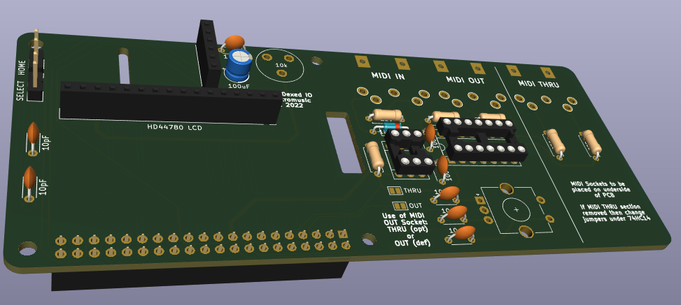
MiniDexed RPi IO Board (HD44780 Version)
Again starting a new KiCad project from the Raspberry Pi 40-pin extension board template, this is the circuit I’m working with for this one.
Schematic Notes:
- This is using the same PCM5102, rotary encoder, and switches as above (although I’ve just realised I never swapped the schematic and pcb over to use the GY-PCM5102 module symbol and footprint – oh well, for this board it is a 6-way set of headers!).
- This uses the “data interface” version of the HD44780. I did think about using the I2C version, but thought this would be the simplest case to build if it could be made to work.
- There is MIDI IN, OUT and (optional) THRU.
- The MIDI circuit borrows heavily from Clumsy MIDI and includes a 74HCT14 hex inverter as an output buffer for OUT and THRU (although it is labelled as a 74HC14 on the schematic and pcb).
- THRU is optional, in which case the unused inputs to the 74HCT14 should go to GND instead (selected by solder jumpers).
- OUT can optionally be changed to a(nother) THRU rather than an OUT, in which case it can be switched via solder jumpers to be connected to RX0 rather than TX0.
To simplify the routing of the PCB, the pinouts for the various components have changed. Here is the pinout being used (this is now quite different to the original MiniDexed pinout).
So this is the design for the pcb that has been sent off for manufacture:
Design notes:
- The PCB is designed to be used with a Raspberry Pi “upside down”. That is, with the connectors at the top, and GPIO at the bottom. This means the USB/RJ45 ports will be on the left hand side, as shown.
- The MIDI THRU section is optional. If only two MIDI sockets are required that part of the board can be cut off along the line indicated. If that is done then the solder jumpers beneath the 74HC14 must be changed as follows:
- Cut the “THRU” jumper (this disconnects the 74HC14 from RX0).
- Solder the “NO THRU” jumper (this connects the unused 74HC14 port to GND).
- The MIDI OUT port can be changed to a THRU too. If the original THRU is removed, this means you can just have MIDI IN and THRU instead of IN and OUT if you wish. If the original THRU is retained, then you can have a MIDI IN and two THRUs. To turn the OUT into a THRU change the two solder jumpers near the H11L1 as follows:
- Cut the “OUT” jumper (this disconnects the OUT circuit from TX0).
- Solder the “THRU” jumper (this connects the OUT circuit to RX0 to make it a THRU).
- Whilst on the subject of MIDI sockets, all three sockets are oriented to go underneath the board so they will go alongside the RPi.
- The optional buttons are not provided on the PCB, but via two sets of headers on the left hand side of the board.
- As mentioned above, annoyingly I forgot to change the PCM5102 footprint to that of a GY-PCM5102 module, so there are no holes for the additional 9-way header. These are not used electrically, but they would have provided some additional physical support. Instead I might solder some header pins and use the plastic pin spacer as a support under the board (but I’ll look into that when I get the boards back).
- I’ve included a simple “preset” pot to control the contrast for the LCD.
- Once again I used a filled zone to create a link to the GND net and provide a ground plane on the rear copper layer of the board. Note that I left a cut-out under the traces to the THRU part of the circuit, to reduce the chance of a short if the board is cut off at this point.
- Most LCD1602/HD44780 modules are 5V parts, with 5V required to ensure the LCD actually illuminates successfully. However, as described here, it is usually ok for a 3V3 output to drive a 5V input, so as long as the LCD isn’t attempting to drive the IO pins for the Pi, the Pi should be fine talking 3V3 to the LCD. So that is the approach I’m taking. It does mean that this won’t accept a 3V3 LCD module. But in all this, remember my level of electronics experience, and make up your own mind…
Manufacturing
Both boards should be built using the standard, cheapest manufacturing options. Both are fine with a 6/6 mil constraint on track width and separation.
The second board is somewhat larger than the common “cheap” tier. For me, all my other boards were $4.60 plus postage for 10 boards, but the larger one has jumped up to around $27 plus postage.
On the back of my first blog post, having used Seeed Fusion to produce my first boards, they sent me some money off vouchers, so I’ve used them once again here. That was particularly welcome given the increased cost of the larger board!
I still don’t really have a space to store these designs. But I’ll update this post when I do!
Closing Thoughts
Although either of these designs could potentially be used in a case to make a nice, small, self-contained unit, I can’t guarantee that the spacing of connectors and components will really allow it. I’m also not sure what will be required in terms of cooling for the Pi, so I’ll have to see how I get on. It may be that I’ll need more spacing between the Pi and the IO board.
I’m still learning with KiCad, so am fully expecting continued mistakes or odd design choices, but I think both of these will be interesting to try.
Update: mistakes already spotted since sending them off:
- The afore-mentioned GY-PCM5102 footprint error.
- Labelling on the board states 74HC14 and it really has to be a 74HCT14.
So that is the walk-through of the design of these boards. Of course I won’t really know if they are successful until I get the boards back from manufacturing!
Kevin
#hd44780 #midi #minidexed #pcb #pcm5102 #raspberryPi #ssd1306
Show Original Post
w (@w@tilvids.com)
CutiePi Review - The Raspberry Pi Powered iPad Mini
https://tilvids.com/w/omajusQXdqpfxMFCtSw2qF
Show Original Post
2022 (@2022@www.kernel-error.de)
Kodi auf dem Raspberry Pi 4: Ruckelfreie Wiedergabe einrichten
Kodi auf dem Raspberry Pi 4: Cache-Tuning fuer ruckelfreie Wiedergabe von NFS-Streams. Update fuer Kodi 21 (Omega) und LibreELEC 12: advancedsettings.xml wird ignoriert, Cache-Werte muessen jetzt in guisettings.xml gesetzt werden.https://www.kernel-error.de/2022/01/18/kodi-auf-dem-raspberry-pi-4-wiedergabe-stockt/
Show Original Post